The power factor regulator is designed to improve the control of reactive power compensation. Continuously detecting the system's reactive power and then compensating by switching capacitor banks is how reactive power compensation is done. The sensitivity setting optimizes the switching speed.
A 12-step Power Factor Regulator (PFR) is a device that regulates capacitor banks to increase an electrical system's power factor. To maximize reactive power compensation, the Selec brand provides a range of power factor controllers with automatic step switching. Essential Elements of a Select 12-Step Power Factor Regulator:
Automatic step switching: This feature turns on or off capacitor banks in response to power factor readings in real time.
12-step control: By controlling up to 12 capacitor banks, this feature enables precise correction.
Display & Monitoring: An LCD/LED screen shows the step status, power factor readings, and alarms.
Harmonic analysis: To avoid overcompensation, certain models identify harmonics.
A 12-step power factor controller from the EPCOS BR6000 series is intended to maximize reactive power compensation in electrical systems. In order to maintain the desired power factor, improve energy efficiency, and lower reactive power charges, this controller measures the actual power factor and connects or disconnects capacitor stages.
Important attributes: User Interface: Multilingual, menu-driven operation with a plain language display. Display: 2 x 16-character illuminated graphic display. Extra Features: Temperature monitoring, automatic initialization, maximum line parameter storage, and display of voltage and current harmonics.
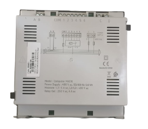
The state-of-the-art regulators of the MAX Series have been designed to offer simple and efficient regulation features. The whole range of computer regulators is based on CIRCUTOR's FCP system (Fast Computerized Program), offering a set of unique performance features. Its main features are as follows:
Shows by display: cos φ, voltage, current, THD(I) and, besides, records in memory maximum values for voltage and current provides the “phase selection” function, that allows the user choosing the power line phase where the measuring current transformer (C.T.) has been placed in allows viewing in display the variation of cos φ, line current and THD(I), when manually connecting or disconnecting capacitor steps.
Indication by display or through relay output of following alarm conditions: Compensation failure, Over-compensation, Over-voltage, Over-current, C.T. not connected or open, Line current below measurable value.
Applications
The computer MAX regulator is ideal to compensate unbalanced installations where the ease or programming, robustness and accuracy are vital requirements. Its programming system is simple and intuitive, making it very easy for the user to install and maintain it.
The state-of-the-art regulators of the MAX Series have been designed to offer simple and efficient regulation features. The whole range of computer regulators is based on CIRCUTOR's FCP system (Fast Computerized Program), offering a set of unique performance features. Its main features are as follows:
Shows by display: cos φ, voltage, current, THD(I) and, besides, records in memory maximum values for voltage and current provides the “phase selection” function, that allows the user choosing the power line phase where the measuring current transformer (C.T.) has been placed in allows viewing in display the variation of cos φ, line current and THD(I), when manually connecting or disconnecting capacitor steps.
Indication by display or through relay output of following alarm conditions: Compensation failure, Over-compensation, Over-voltage, Over-current, C.T. not connected or open, Line current below measurable value.
The computer MAX regulator is ideal to compensate unbalanced installations where the ease or programming, robustness and accuracy are vital requirements. Its programming system is simple and intuitive, making it very easy for the user to install and maintain it.
.jpg)
_-_Copy.jpg)
 Cash on delivery available
 Returns allowed
.jpg)
_(450_x_450)11.jpg)
_(450_x_450)1.jpg)
_(450_x_450)12.jpg)
_(450_x_450)1.jpg)
_(450_x_450).jpg)