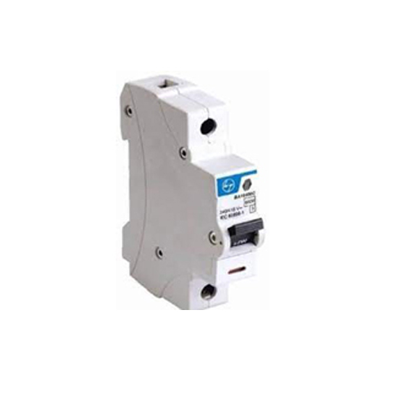
The purpose of ABB's miniature circuit breakers (MCBs) is to guard against overloads and short circuits that could harm electrical circuits. To avoid possible risks, they immediately cut the electrical circuit under unusual circumstances.
Important attributes:
- High Reliability: ABB MCBs are renowned for their longevity and reliable operation.
- Safety: Made to keep electrical installations safe by guarding against short circuits and overloads.
- Broad Range: To accommodate diverse applications, it is offered in a variety of types and ratings.
- Simple Installation: DIN rails can be quickly and easily installed thanks to the modular architecture.
Click here > Catalogue
Standard product IEC/EN 60898-1
General Data
Standards IEC/EN 60898-1
Poles 1P, 2P, 3P, 4P
Tripping Characteristics B, C
Rated short-circuit capacity (Icn) 6kA & 10 kA
Rated frequency 50/60Hz
Rated voltage Ue 1P: 230/400 V AC, 2P, 3P, 4P: 400 V AC
Reference temperature for tripping characteristics 30°C
Energy limiting class (B-,C-Curve) 3
Rated current In B & C: 6, 10, 16, 20, 25, 32, 40, 50, 63 A
Load line reversibility Yes
Min. operating voltage 12 V AC
Rated impulse withstand voltage Uimp. (1.2/50μs) 4 kV (Test Voltage 6.2kV at sea level, 5.8kV at 2000m)
"Max. Loop impedance Zs at various rated current B Curve: 6A=7.3, 10A=4.3, 16A=2.6, 20A=2, 25A=1.5, 32A=1.1,
C curve: 6A=3.5, 10A=2.0, 16A=1.1, 20A=0.8, 25A=0.6, 32A=0.4, 40A=0.3, 50A=0.2, 63A=0.1
Dielectric test voltage 2 kV (50/60Hz, 1 min.)
Overvoltage category III
Rated insulation voltage Ui acc. to IEC/EN 60664-1 250 V AC (phase to ground), 440 V AC (phase to phase)
Pollution degree 2
Mechanical Data
Contact position indication White Marking on toggle ('I' ON / 'O' OFF)
Protection degree acc. to EN 60529 IP20 & IP40 in enclosure with cover
Mechanical endurance In < 32A>
Ambient temperature (with daily average ≤ +35°C) -25 ... +55°C
Tropicalisation acc. to IEC/EN 60068-2-30 Severity 2 Cyclic test with 55°C/90-96% and 25°C/95-100%
Storage temperature -40 ... +70°C
Housing Insulation group II
Installation
Terminal Cage terminal
Cross-section of conductors (top / bottom) Solid, Stranded 35 mm⊃2; / 35 mm⊃2;
Flexible 25 mm⊃2; / 25 mm⊃2;
Cross-section of busbars (top / bottom) 10 mm⊃2;
Busbars type Pin and Fork Type Busbar provision
Tightening Torque 2 Nm
Screwdriver No. 2 Pozidrive
Mounting On DIN rail 35 mm
Mounting position Any
Supply Any
Cable Length 12.5mm
Dimensions and weight
Mounting dimensions acc. to DIN 43880 Mounting dimension 1
Pole dimensions (H x D x W) (per pole) 88 x 69.2 x 17.5 mm
Pole weight (per pole) 110Gms
Approvals
CE marking approved Yes
MOIAT LVE Certification Yes
MOIAT RoHS Certification Yes